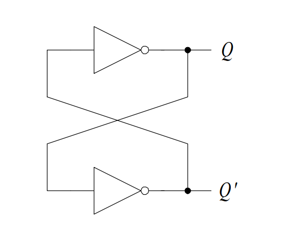
The simplest sequential circuit or storage element is a bistable element, which is constructed with two inverters connected sequentially in a loop as shown in Figure 1. It has no inputs and two outputs labeled Q and Q’. Since the circuit has no inputs, we cannot change the values of Q and Q’. However, Q will take on whatever value it happens to be when the circuit is first powered up.
Assume that Q = 0 when we switch on the power. Since Q is also the input to the bottom inverter, Q’, therefore, is a 1. A 1 going to the input of the top inverter will produce a 0 at the
output Q, which is what we started off with. Similarly, if we start the circuit with Q = 1, we will get Q’ = 0, and again we get a stable situation.

A bistable element has memory in the sense that it can remember the content (or state) of the circuit indefinitely. Using the signal Q as the state variable to describe the state of the circuit, we can say that the circuit has two stable states: Q = 0, and Q = 1; hence the name “bistable.”
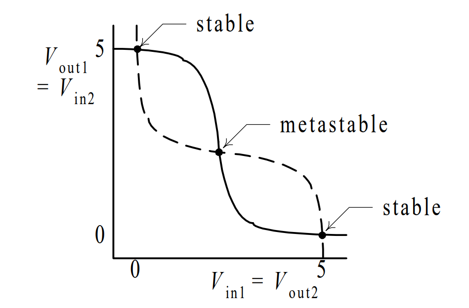
An analog analysis of a bistable element, however, reveals that it has three equilibrium points and not two as found from the digital analysis. Assuming again that Q = 1, and we plot the output voltage (Vout1) versus the input voltage (Vin1) of the top inverter, we get the solid line in following Figure . The dotted line shows the operation of the bottom inverter where Vout2 and Vin2 are the output and input voltages respectively for that inverter.

shows that there are three intersection points, two of which corresponds to the two stable states of the circuit where Q is either 0 or 1. The third intersection point labeled metastable, is at a voltage that is neither a logical 1 nor a logical 0 voltage.
Nevertheless, if we can get the circuit to operate at this voltage, then it can stay at that point indefinitely. Practically, however, we can never operate a circuit at precisely a certain voltage. A slight deviation from the metastable point as cause by noise in the circuit or other stimulants will cause the circuit to go to one of the two stable points.
Once at the stable point, a slight deviation, however, will not cause the circuit to go away from the stable point but rather back towards the stable point because of the feedback effect of the circuit.
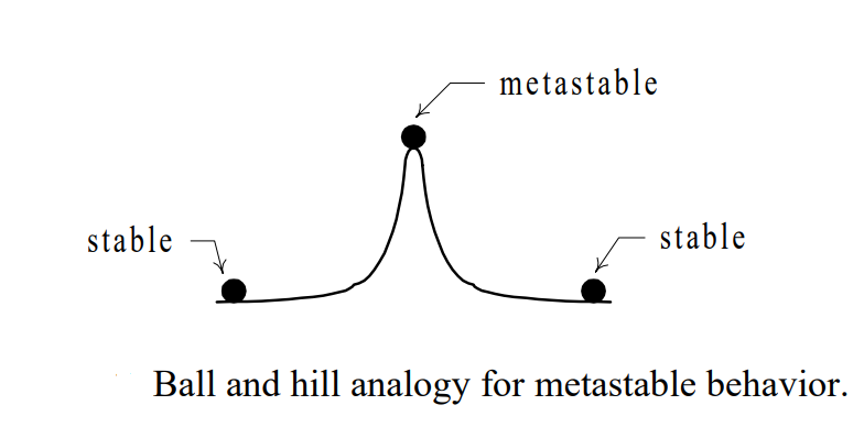
An analogy of the metastable behavior is a ball on top of a symmetrical hill as depicted in Following Figure .

The ball can stay indefinitely in that precarious position as long as there is absolutely no movement whatsoever. With any slight force, the ball will roll down to either of the two sides. Once at the bottom of the hill, the ball will stay there until an external force is applied to it. The strength of this external force will cause the ball to do one of three things.
If a small force is applied to the ball, it will go partly up the hill and then rolls back down to the same side. If a big enough force is applied to it, it will go over the top and down the other side of the hill. We can also apply a force that is just strong enough to push the ball to the top of the hill. Again at this precarious position, it can roll down either side.
We will find that all latches and flip-flops have this metastable behavior. In order for the element to change state, we need to apply a strong enough pulse satisfying a given minimum width requirement. Otherwise, the element will either remain at the current state or go into the metastable state in which case unpredictable results can occur.